Draft it Help System
The complete Help system for Draft it is available on these pages.
Available in: FREE, Plus, PRO & Architectural
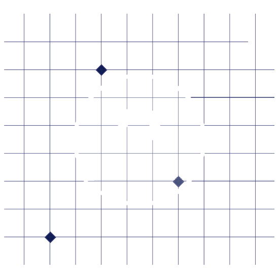
Next we will create the door openings. In the following diagram the portions of the lines to be removed are shown as dotted.
Before we can use the Trim / Extend command to modify the individual lines of the rectangle we will need to explode the polyline that the rectangle is made out of. Exploding the polyline will convert the polyline that the rectangle is made of into individual lines.
To explode the rectangles first select the outer rectangle then click on the
explode
 button, once this is complete please select the inner rectangle and click on the
explode
button.
button, once this is complete please select the inner rectangle and click on the
explode
button.
Now that the rectangles have been exploded into individual lines we can move on to using the trim extend functionality to modify the lines.
Select the trim extend button
 and the prompt reads:
Give Arc/Line to Trim/Extend:
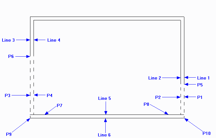
We need to select the line near to the end to be modified so click on 'Line 1' near to P1. At this point the system toolbar changes to display either
Distance Input
 or Snap input
 depending upon the last use. If not set make sure the Distance
option is picked.
Drag the cursor upward and click at P5 when the dimension reads '-1010.00' (the opening is 910 + 100 for the wall thickness).
depending upon the last use. If not set make sure the Distance
option is picked.
Drag the cursor upward and click at P5 when the dimension reads '-1010.00' (the opening is 910 + 100 for the wall thickness).
Right click to repeat the command and click on 'Line 2' near to P2. Make sure the Snap input
( ) is set and snap to the modified end of 'Line 1' (P5) so that this line end is adjusted to the same horizontal position.
Repeat the command again, select 'Line 3' near to P3. Make sure the Distance Input
( ) is set and drag the cursor upward and click at P6 when the dimension reads
'-1920.00' (the opening is 1820 + 100 for the wall thickness).
) is set and drag the cursor upward and click at P6 when the dimension reads
'-1920.00' (the opening is 1820 + 100 for the wall thickness).
Repeat again and click on 'Line 4' near to P4. Make sure the Snap input
() is set and snap to the modified end of 'Line 3' (P6)
so that this line end is adjusted to the same horizontal position.
'Line 5' needs to be extended by 100mm at both ends. Repeat the command, select 'Line 5' near to P7 and snap to P9.Finally repeat again then select 'Line 5' near to P8 and snap to P10.
We have now created the openings and need to close the wall ends. Select the Line button
 and make sure the Snap input
() is set. Draw a line between the ends of 'Line 1 & 2' (at P5).
Then another between 'Lines 3 & 4' (at P6) then two more to close the ends of the wall defined by 'Lines 5 & 6' (at P9 & P10).
Remember after each line is drawn right -click to cancel line drawing and again to repeat the command.
and make sure the Snap input
() is set. Draw a line between the ends of 'Line 1 & 2' (at P5).
Then another between 'Lines 3 & 4' (at P6) then two more to close the ends of the wall defined by 'Lines 5 & 6' (at P9 & P10).
Remember after each line is drawn right -click to cancel line drawing and again to repeat the command.