Datum Chain Dimension
Available in: Pro, Architectural
Datum dimensioning allows a datum position to be set using the Set Datum command  . Datum dimensions can be added to the drawing which measure from this datum point.
Datum Chain dimensioning works in a similar way to the Datum Dimension except that all of the text points are aligned with each other. This is means that after the first datum dimension is drawn the subsequent dimensions are added by simple clicking the next dimension point. This can be useful if either all of the dimensions need to be aligned or simply to make the creation of the dimensions quicker.
Once selected the Ribbon changes to show the current dimension properties and the command prompt reads:
Give Dimension Point:
Indicate the dimension point using any of the snaps and input options as shown in the first image below (This is P1 in the second image).
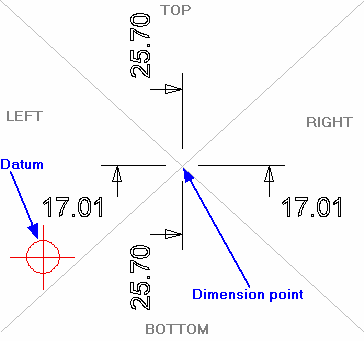
Give Text Point:
The dimension text and leader line move with the cursor and the dimension will flip between the TOP, RIGHT, BOTTOM & LEFT quadrants separated by the grey lines in the diagram below. Once the desired position is achieved click to accept it (This is P2 in the second image).
If no datum has been set, the system will take the drawing origin as the datum. If a datum point is added to the drawing or moved then the datum dimensions can be updated automatically by selecting the Refresh command.
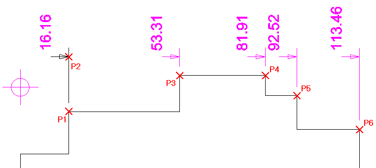
The first datum dimension is drawn, highlighted in the next image. The prompt now reads:
Give Next Point:
Indicate the next point to dimension to (P3) using any of the snaps and input options. The next datum dimension is drawn. This prompt repeats until the command is cancelled allowing subsequent dimensions to be added with a single point. You can see in the example below that points P4, P5 and P6 were clicked and that all of the dimensions line up with the first dimension point (P2).