Draft it Help System
The complete Help system for Draft it is available on these pages.
Available in: FREE, Plus, PRO & Architectural
Now to add the sink which is positioned directly under the window on the upper wall. Use Zoom Window
 to close in on the area of the drawing shown below.
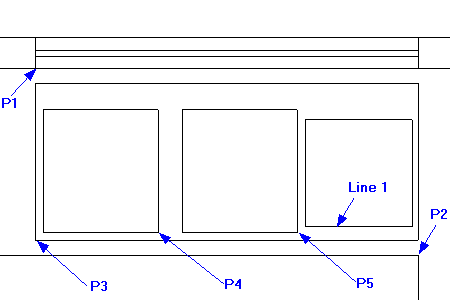
Select the Rectangle button
 and go Relative to P1, type '
0' and
and go Relative to P1, type '
0' and
 for the X value, then '-50' and
for Y. This is the 1st rectangle corner. Now go Relative
to P2, type ' 0' and
for the X value, then '50' and
for Y, this is the 2nd corner.
for the X value, then '-50' and
for Y. This is the 1st rectangle corner. Now go Relative
to P2, type ' 0' and
for the X value, then '50' and
for Y, this is the 2nd corner.
Select the Rectangle
again and go Relative
to P3, type '25' and
then '25' and
for the first corner, then '375'
and '400'
for the second corner.
Repeat this method to create the next two rectangles. The following describes the points and values you need.
Relative to P4, 80 in X and 0 in Y then 375 in X and 400 in Y.
Relative to P5, 25 in X and 20 in Y then 350 in X and 350 in Y.
We will now create 6 lines parallel to 'Line 1' to represent the draining board of the sink unit.
Select Offset
 , click on 'Line 1' and type 50 into the
Distance Input field and click to accept.
, click on 'Line 1' and type 50 into the
Distance Input field and click to accept.
Repeat this procedure 5 more times but each time click on the offset created last time, the offset distance is now preset to 50 (until unlocked) so you can just click anywhere to accept.
Select the Circle command
 to create the plug hole. Go Relative
to P4, type '-187.50' and
and '200' for the centre point. For the radius point press any of the arrow keys and type 20 then
. Repeat this relative to P5 for the other plug hole.
to create the plug hole. Go Relative
to P4, type '-187.50' and
and '200' for the centre point. For the radius point press any of the arrow keys and type 20 then
. Repeat this relative to P5 for the other plug hole.
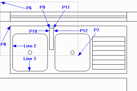
Select the Fillet command
 , click on 'Line 2 & 3' and type in 50 and press
. Repeat this for other sink corners so that the sink unit is as shown here.
Now use Zoom Window
to close in on the area defined by points 'P6 & P7'.
, click on 'Line 2 & 3' and type in 50 and press
. Repeat this for other sink corners so that the sink unit is as shown here.
Now use Zoom Window
to close in on the area defined by points 'P6 & P7'.
Now as described earlier in the topic create another Rectangle
as follows.
Relative to P8, 420 in X and -20 in Y then 40 in X and -220 in Y.
Select Line
 and pick the 'End' point at P9 for the start position. Press
 type '120'
, press
type '120'
, press
 type '40'
, make sure Snap
(
type '40'
, make sure Snap
( )
is set, now move across to the right and select the 'Perpendicular' point near to P10.
)
is set, now move across to the right and select the 'Perpendicular' point near to P10.
Select Line
pick the 'End' point at P11 for the start position. Press
 type '120'
, press
type '40'
move across to the left and select the 'Perpendicular' point near to P12.
type '120'
, press
type '40'
move across to the left and select the 'Perpendicular' point near to P12.
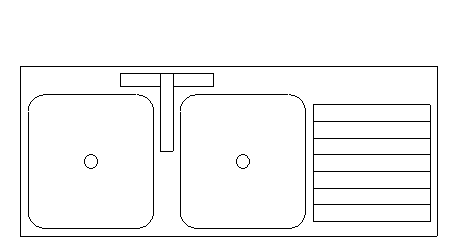
The sink unit is now complete.