Draft it Help System
The complete Help system for Draft it is available on these pages.
Available in: Architectural
Use this command to insert an opening into a wall. Select the 'Opening' button
 and the following dialog box appears.
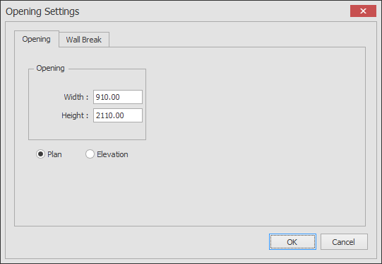
The dialog box is spilt into 2 tab pages. Set the values as required.
Opening Tab
Opening Width - This is the width of the opening created in the wall.
Opening Height - This is the height of the opening which is used in automatic elevation creation and the 3D Viewer.
Plan - This option specifies that a plan view of the opening will be used.
Elevation - This option specifies that an elevation view of the opening will be used.
Wall Break Tab
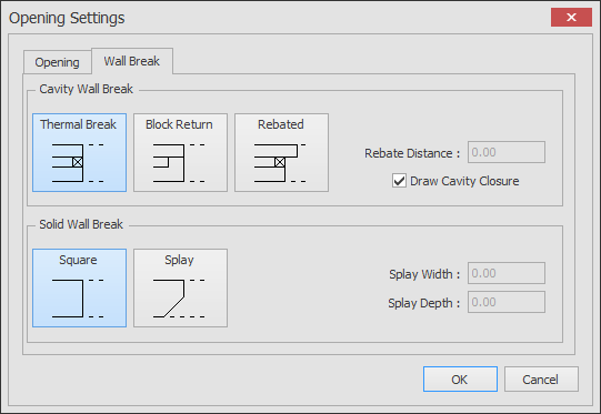
Select the wall break type for cavity and solid wall types when inserting doors, windows and openings. The appropriate value boxes are available for some of the options. Set the requirement and click OK. These settings remain until changed, and are stored with the individual door, window and opening.
Once all of the settings are correct in the Opening and Wall Break tab pages click OK.
The insertion procedure differs depending on the status of the Plan/Elevation option :-
Plan option
The dialog box closes and the command prompt reads:
Give Insertion point on wall:
At this point if you move the cursor over a wall dynamic dimensions are displayed to allow you to position the opening accurately, these dimensions update as you move the cursor (You can modify the increment of the dimension movement).
If you move the cursor past the centre line of the wall the dimensions flip and reference the appropriate points on that side of the wall, see below.
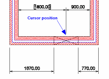
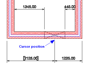
In each of the pictures above you will see that the dimension text of one of the four dynamic dimensions is enclosed in brackets, this is the controlling dimension.
It is possible to define the opening position by typing a value into the Distance Input box.
If a value is typed into this box the padlock button to the right locks
 . This locks that dimension and the cursor can only be moved across the wall to flip the dimension. It is possible to change the controlling dimension by hitting the
 key on the keyboard.
Doing this moves the controlling dimension to the other end of the wall. Therefore it is possible to specify any of the four dynamic dimensions as the controlling dimension by moving the cursor either
side of the wall and using the
key.
If the value entered is greater than the wall length plus the opening width then the controlling dimension value is adjusted to show the maximum allowable distance.
To change the value simply modify the value in the Distance Input box.
To clear the value entered and allow the opening to be moved 'freely' along the wall click the padlock button again so it is displayed as follows
key on the keyboard.
Doing this moves the controlling dimension to the other end of the wall. Therefore it is possible to specify any of the four dynamic dimensions as the controlling dimension by moving the cursor either
side of the wall and using the
key.
If the value entered is greater than the wall length plus the opening width then the controlling dimension value is adjusted to show the maximum allowable distance.
To change the value simply modify the value in the Distance Input box.
To clear the value entered and allow the opening to be moved 'freely' along the wall click the padlock button again so it is displayed as follows
 .
.
You can modify the Opening justification if required using the justification option box
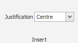 in the Ribbon .
This justification is orientated when viewing the external wall face, see below.
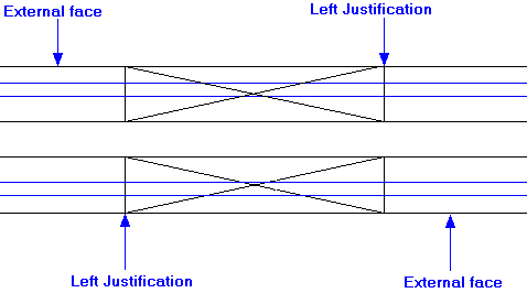
Simply click into place once the desired position is achieved. The structural opening is created and the wall ends are capped.
The command automatically repeats to allow the opening to be placed in additional positions.
See Modifying/Moving a Opening for information on how an opening can be edited.
Elevation option
The dialog box closes and the command prompt reads:
Give Insertion Point:
The insertion procedure is the same as for insertion of any other Symbol.
The selected opening elevation is attached to the cursor for placement anywhere on the drawing using any of the snaps and input options.
NOTE: The opening elevation is non-intelligent Symbol unlike the plan view of the same which is remembers the wall it is inserted into. Therefore after inserting an elevation view of a opening the command does not repeat. This is because after clicking 'OK' in the dialog box the program uses a standard Insert Symbol function to place the opening. Because the opening elevation is non-intelligent Symbol it can only be modified with the same options as with Modifying/Moving any other Symbol. i.e. you cannot double-click on the opening elevation and return to the 'opening' dialog box.