Product Documentation
Draft it Help
Select the category below to quickly find the help you need.

Available in: Architectural
Use this command to create an elevation.
Select the 'Elevation' button
 and the command prompt reads:
Give wall on which elevations will be based:
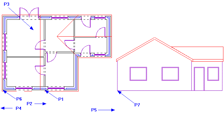
Simply click on the wall the elevation is to be based on (P1 in the example diagram below), i.e. if you required an elevation of the front of your building you would pick one of the wall lines along the front of the building. The viewing direction will be perpendicular to this wall. The command prompt reads:
Give observation point for elevation:
This would generally be a point on the outside of the building. This point partly determines what is included in the view being produced. The point given should therefore be far enough away from the outside to include any projection of the building you wish to be drawn (P2 in the example diagram below). The command prompt reads:
Give Depth of field:
This point determines how far through the building the command looks for relevant entities. When giving this point you should include all ridge lines where you require the roof to be entirely included (P3 in the example diagram below). If a ridge line is not included in the selection the roof will be cut off at the point indicated. In most cases this point should not extend past the opposite wall so that doors and windows in that wall are not included. The command prompt reads:
Give left extent of elevation:
This point determines how much of the plan view to the left of the observation point to include in the drawn elevation. This allows you to produce a partial view if required. In other words if you wish to cut off the end of the building from the elevation, you would pick a point that does not include the entire extents of the given view to the left. If the entire elevation view is required then the point given should be some where past the left extents of the plan (P4 in the example diagram below). The command prompt reads:
Give right extent of elevation:
This point works in the same way as the left extents, but for the right hand side of the building. Therefore the same rules apply for what is or is not drawn, depending of the point given. Again if the entire elevation is required a point beyond the right extents of the building should be given (P5 in the example diagram below). The command prompt reads:
Give reference point on plan:
This point is the point used to position the elevation on the drawing. It is also used for lining up multiple storeys and therefore should be a common point which can be picked on all floors, e.g. the lower left corner of the building (P6 in the example diagram below). The command prompt reads:
Give position of reference in elevation:
This point is the point from which the elevation will be constructed, or the insertion point (P7 in the example diagram below).
The created elevation is made of standard entities allowing it to be modified 'manually' as required. It is not associated to the plan, therefore if the plan was altered the elevation would have to be re-created to reflect the changes.
Any questions?
Perhaps you need help deciding which of our CAD systems is right for you, or maybe you need to chat with us about our bespoke development service.
Don’t hesitate to get in touch. The Draft it team is dedicated to ensuring you get the best design experience on the market. Whatever you need - call us, email us – we’re here to help.
 +44 1543 419 886
 enquiries@cadlogic.com
 Postal Address Details