Product Documentation
Draft it Help
Select the category below to quickly find the help you need.

Available in: FREE, Plus, PRO & Architectural
Click on vertical line in the diagram here so that its Entity Handles are displayed.
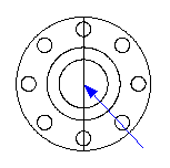
Now click In the status bar click in the 'Style' field and from the list pick the 'Centre line' line type. Draft it asks you to confirm that you wish to change the line style of the current selection, click on 'Yes'.
With the line still selected click in the 'Colour' field on the status bar and pick 'Red' then confirm the change by clicking 'Yes'.
De-select the line by clicking in free space on the drawing.
We have just modified the existing centre line but now we now need to change the current Colour & Layer so that all of the new centre lines are created with the correct settings. Simply click into the 'Colour' field on the status bar and pick 'red' as before. Because no entities are selected the current setting is changed. Repeat this for the 'Style' and set it to 'Centre-line'.
We need to add centre lines to the 12mm holes in the side elevation. This is another opportunity to demonstrate the usefulness of the
Relative feature and
Direct Input. Select the
Line button
 and position the cursor over the 'End' point at P1,
hit the
and position the cursor over the 'End' point at P1,
hit the key.
Now type '-5.00' and press
key.
Now type '-5.00' and press
 (this is the X value) then type '-6.00'(this is the Y value).
Continue using Direct Input
to draw the next line by typing '25' and press
the '0' and
once more.
Right click to cancel line drawing and again to repeat the command.
Position the cursor over the 'End' point at P2, hit the key.
Now type '-5.00' and press
then type '-6.00' . Now type '25' and press
the '0' and
once more.
key.
Now type '-5.00' and press
then type '-6.00' . Now type '25' and press
the '0' and
once more.
Right click to cancel line drawing and again to repeat the command.
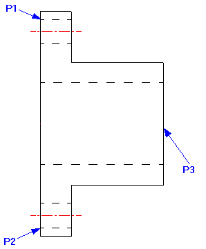
Now position the cursor over the 'Mid' point at P3 (above). Hit the
 key and type '5.00' and
then '0' and
again. Now type '-225.00' and
then '0' and
again. Right click to cancel the line command.
key and type '5.00' and
then '0' and
again. Now type '-225.00' and
then '0' and
again. Right click to cancel the line command.
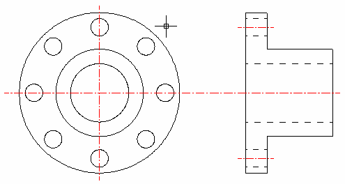
Select the Trim/Extend command
 and click on the vertical centre line near to the top. By default Distance Input
 should be switched on, move the cursor up and click when the dimension reads '5.00'. Repeat this command again and extend the vertical centre line at the bottom end by 5mm. Your drawing should look like this.
Any questions?
Perhaps you need help deciding which of our CAD systems is right for you, or maybe you need to chat with us about our bespoke development service.
Don’t hesitate to get in touch. The Draft it team is dedicated to ensuring you get the best design experience on the market. Whatever you need - call us, email us – we’re here to help.
 +44 1543 419 886
 enquiries@cadlogic.com
 Postal Address Details