Product Documentation
Draft it Help
Select the category below to quickly find the help you need.

Available in: Architectural
The Level command
 is used to set floor heights so that 3D Viewer
views of multiple floor buildings can be created. When the command is selected the following dialog box is displayed.
is used to set floor heights so that 3D Viewer
views of multiple floor buildings can be created. When the command is selected the following dialog box is displayed.
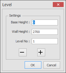
Here the height of the floor (Base Height) and the height of the walls for that floor of the building (Wall Height) can be set. The 'Level No.' of the floor is also set here. The '-' & '+' buttons are used to increment the 'Base Height' and 'Level No.' values. Once the values have been set click on OK and the prompt reads.
Give Reference Point:
Indicate a point on the drawing that can be used as a reference point for the level. This should be a common point appearing in each floor plan or level such as the corner of an external structural wall. The prompt now reads.
Give First Point:
Select one corner of a selection box enclosing the floor area to be included in the level.
Give Second Point:
Select the opposite corner of a selection box enclosing the floor area to be included in the level.
The level is now defined and a dotted box denoting this is drawn on a layer called 'levels'.
The following example shows how to define the Levels for a two story building.
Select the Levels command and make sure the values match the dialog box above, then click OK.
The picture below shows the ground floor and first floor of the building. First we will define the Level detail of the ground floor so click on the external end point of the wall at P1, this is the reference point. The box that encloses this level is defined by clicking approximately at P2 & P3. The level box will be drawn.
Now select the command again. In the dialog box click on the '+' button and the 'Base Height' will automatically change to '2700' (the 'wall height' is added to the 'base height' when this button is pressed). The 'Level No:' is also automatically incremented and should now read '2'. Click 'OK' and select P4 as the reference and P5/P6 as the corners of the box. The second level box will be drawn and would look similar the picture below.
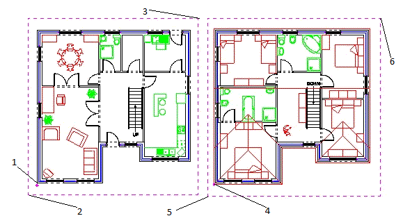
Now that the levels are correctly defined the 3D Viewer will be able to 'stack' the floors so that the building displays correctly.
Any questions?
Perhaps you need help deciding which of our CAD systems is right for you, or maybe you need to chat with us about our bespoke development service.
Don’t hesitate to get in touch. The Draft it team is dedicated to ensuring you get the best design experience on the market. Whatever you need - call us, email us – we’re here to help.
 +44 1543 419 886
 enquiries@cadlogic.com
 Postal Address Details