Product Documentation
Draft it Help
Select the category below to quickly find the help you need.

Available in: FREE, Plus, PRO & Architectural
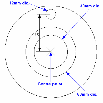
Now will draw the 60mm diameter boss, the 40mm diameter inner bore and the 12mm diameter hole. The diagram here shows how these circles should appear.
So select the Circle command again by clicking the
 button, alternatively you can right click the mouse to repeat the last command.
First the 60mm diameter circle. The prompt reads:
button, alternatively you can right click the mouse to repeat the last command.
First the 60mm diameter circle. The prompt reads:
Give Centre Point:
Place the cursor anywhere on the circle circumference and hit the on the keyboard. The
 symbol is displayed denoting that Draft it has found the circle centre point. Whilst this is displayed click to accept the position. The prompt reads:
Give Radius Point:
Draft it has remembered that the X, Y
 input option was used last time so this remains set for the next point. Drag the cursor to the right and click to accept when the X dimension reads 30.00 and the Y reads zero.
Now for the 40mm diameter circle, either repeat the above procedure (using the key)
to select the existing centre point or move the cursor toward the actual circle centre and click when the
symbol is displayed. After picking the centre drag the cursor to the right and click to accept when the X dimension reads 20.00 and the Y reads zero.
key)
to select the existing centre point or move the cursor toward the actual circle centre and click when the
symbol is displayed. After picking the centre drag the cursor to the right and click to accept when the X dimension reads 20.00 and the Y reads zero.
Now to draw the first 12mm diameter circle which is going to be the topmost hole 45mm (the PCD is 90mm) above the centre point of the existing circles. Here we can use the Draft it Relative feature to define this position.
Reselect the Circle command once more and move the cursor over the existing centre point. When the
symbol is displayed hit the ; key and the
X, Y dynamic dimensions will be activated .
Click to confirm the new point when the values read X0.00, Y45.00.
; key and the
X, Y dynamic dimensions will be activated .
Click to confirm the new point when the values read X0.00, Y45.00.
We now need to define the radius point 6mm away from the centre, however the Cursor Increment is set to 5mm. Rather than resetting this value to something more suitable we can use
Direct Input to enter the X & Y values required. Now simply hit
 (you will notice a small input box next to the cursor) and then hit
 This is the 'X' co-ordinate. For the 'Y' value hit
 and then
. The 12mm circle should now be drawn.
and then
. The 12mm circle should now be drawn.
Any questions?
Perhaps you need help deciding which of our CAD systems is right for you, or maybe you need to chat with us about our bespoke development service.
Don’t hesitate to get in touch. The Draft it team is dedicated to ensuring you get the best design experience on the market. Whatever you need - call us, email us – we’re here to help.
 +44 1543 419 886
 enquiries@cadlogic.com
 Postal Address Details